Wednesday, September 20, 2006

A Collection Of "235" Screen Shots

In video projection of the "scope" format, the aspect ratio will actually be 2.37:1, not 2.35:1 as it is more commonly known. This is because when you take the light beam [1.78:1 rectanglet of light] from a 16:9 projector and pass it through the 33% stretch lens used in video applications, the new shape of the light rectangle is now 2.37:1...

All of the screen shots in this BLOG are from a low resolution [480P] LCD projector. To see some new screen shots that were created using the Aussiemorphic Lens and a 720P DLP click HERE...

Star Wars Episode III - Revenge Of The Sith

R2D2 abord a Jedi Fighter
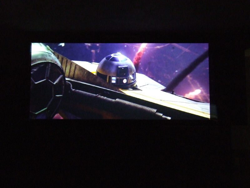
I chose this shot for the geometric shapes like the R2D2's dome head...

Obi-wan's fighter
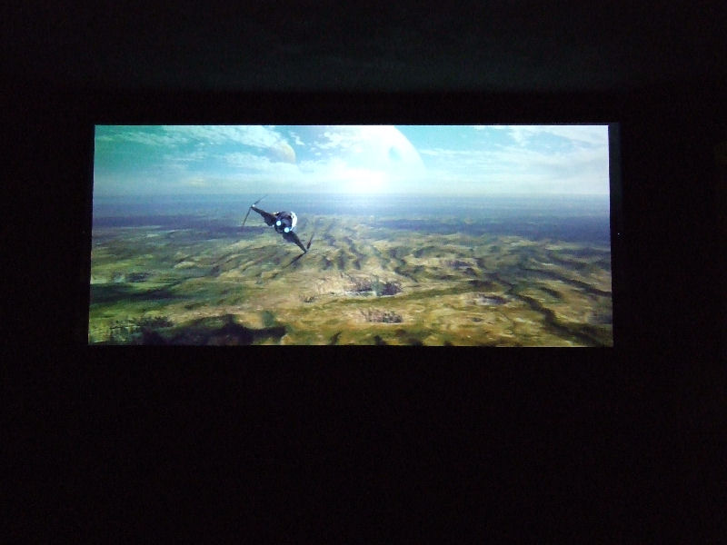
This shot was chosen for the uniformity of focus across the screen. It too has some great geomtric shapes.

General Grevious
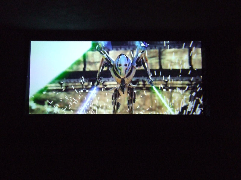
This shot was chosen as a "re-do" of an earlier attempt to get the full 33% stretch. This is how it meant to be seen...

Clone Trooper
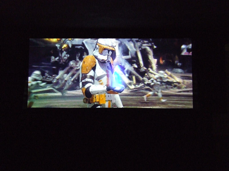
This shot is also another "re-do" for the same reasons I posted above...

Darth Vader
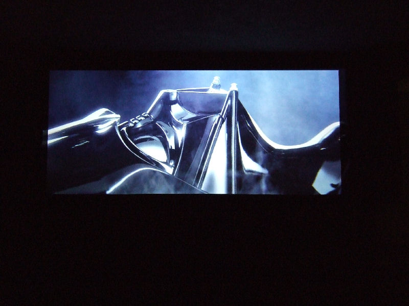
So often when screen shots are taken, the image is always bright. Here I am trying to show shadow detail...

The Animatrix - Last Flight Of The Osirus...

These images were the very first screen shots captured using the "Aussiemorphic Lens"...

The Lord Of The Ring - Fellowship Of The Ring

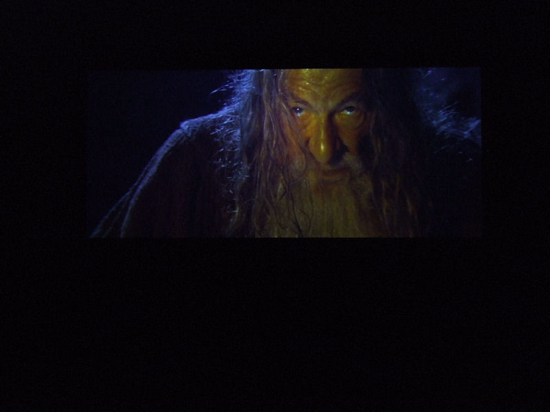
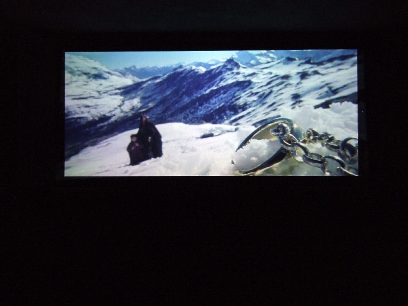
This is another "re-do" as originally I could not get the true amount of stretch, so this image only had an Aspect Ratio of 2.25:1. Here it is at 2.35:1, the way it was meant to be seen...

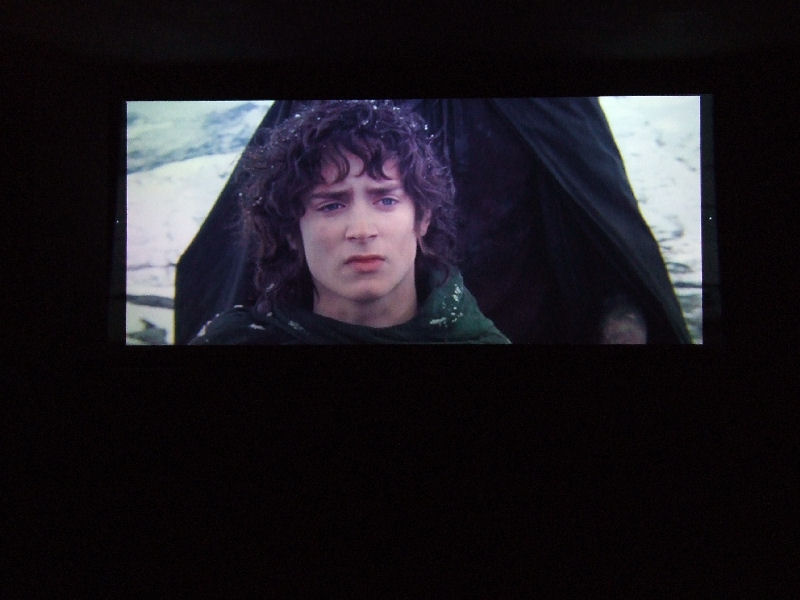
Another "re-do" and again this time in the correct AR...

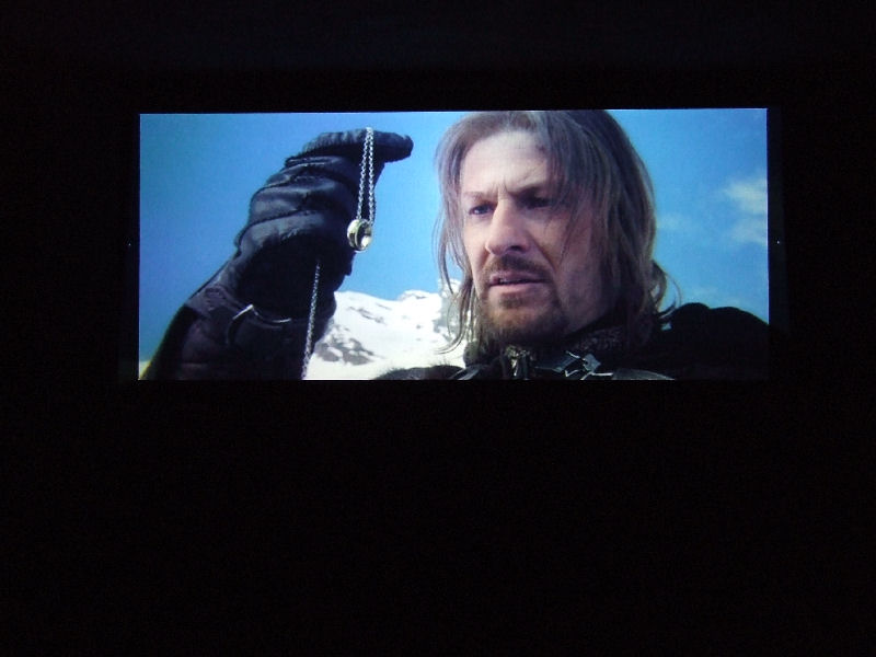
This is a really good. Good colour, focus and very little CA...

The Incredibles
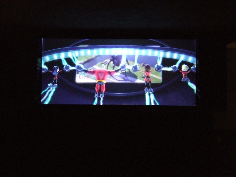
I took this shot to compare the Aussiemorphic Lens to another DIY lens for geometry...

The Fifth Element

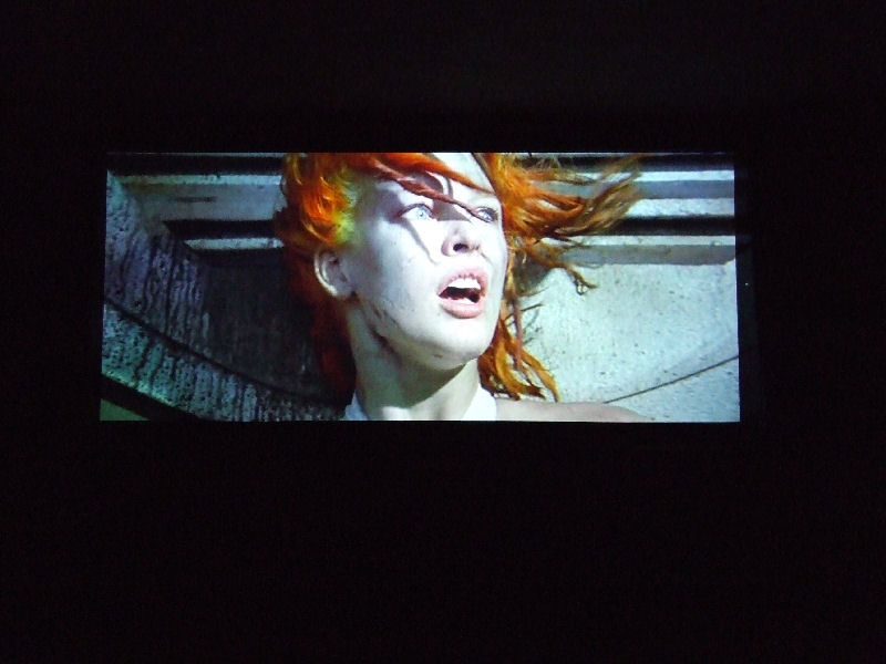
A very popular film and a great test for uniform focus from edge to edge...

Mark

Back To The Top

Back To The SRT [Small Roon Theory]


As I have sold my home, I am now in the process of redesigning my home theatre yet again for a small room.

My first dedicated small room was based on a theory - If mixing booths for professional multi-channel sound can be small enough to fit into a location van, why could a home theatre not be designed small as well?

And so began the SRT - SMALL ROOM THEORY.

When I first purchased the house, part of the deciding purchase factor was that it needed a small room that I could convert into a dedicated cinema.

The home I bought did have a small room, but after several years in there, I decided that I wanted a larger room, a room that I could share with family and friends.

THE SMALL ROOM THEORY
The SRT was just 3600mm long, 2200mm wide and just 2100mm high. It was actually a tool shed that I completely stripped and remodeled. During the retrofit, I lined the wall cavities with foam and insulation to help reduce sound transmission - both from out side in as well as inside to the outside...

The room was painted flat back - all 6 surfaces, and was dubbed the CAVE with good reason - it had TOTAL black out capabilities.

The layout was based on the ITU-R from the centre of the room with the LCR speakers located at seated ear height, with C at 0 degrees and L and R at +/-30degrees. The Surrounds (only 2 at the time) were positioned on the side walls at +/-110degrees and about 1500mm off the floor.

I built a stage for the screen (1.78:1 at the time) with recessed speaker cavities to allow a flush finish for the LCRs. The Surrounds were wall mounted using an extruded aluminium rail (which has become a part of the CAVX SPEAKER design). The EQ rack was in the rear left corner and required the addition of an IR repeater.

There was only one row of two seats, so not very friendly for entertaining groups...though one night, I did manage to squeeze 6 people in there...

Seeing as how at the time, I had two 7.1 systems, I decided to set a multi channel music only system in a the lounge room (that wasn't being used for anything else).

I then decided that I liked the larger space, and that I should integrate a video system as well.

THE PLAN FOR THE NEW ROOM
Above is a the plan I had used in my cinema for over 12 months. The room was 5.6m x 3.8m x 2.4m, and I decided to set up my new cinema. Originally there was to be 2 levels of riser, but in the end, only one was used...

THE FRONT STAGE and 2.37:1 "SCOPE" SCREEN
The early install of the 235 screen...The EQ Rack is behind the screen so that the lights of the displays are not in the site line. An IR repeater was installed so that I could operate the components from the comfort of my back row seat.

Since this shot was taken, a new masking system including a version of the US "GULL WING" side masking had been added. The new masking systems allows the screen to bow in to correct the optical errors such as pincushion that are bi-products of the anamorphic lens...

THE SEATING

There was two rows of seats and the back row was elevated 300mm. This gaves an excellent site line to both the screen and the LCR speakers. The grey carpet nicely matched the lower wall and the blue seats matched the upper side walls. The ceiling was the same grey as the lower wall...

Mark

Back To The Top

Wednesday, September 13, 2006

The CAVX Approach To Room Design

Home Theatre is about recreating the Cinematic Audio Visual eXperience in the home. To do this properly, one must understand at least the very basics of how a real cinema works.

Home Theatre follows the guidelines of a real cinema layout in that we use three speakers for the screen channels [Left Centre Right], but rather than an array of speakers on the side walls [extending to the back wall] we use just two surround speakers [located at the sides of the listening position]. Like real cinemas, the speaker layout also includes a sub-woofer [for the low bass extension as well as the LFE channel].
A Look At A Real Cinema
This photo was taken in a real cinema that is equipped for Surround EX playback. Your can see the multi-speaker arrays on both the side and rear walls. This cinema has a total of 18 surround speakers [6 on each wall] to form a very enveloping sound field. Note the sound absorption panels on the back wall.

With the introduction of Extended Surround systems in the home came an additional pair of speakers on the back wall. I am a believer that the four surround speakers should be the same make and model [the three LCR screen channel speakers should also be identical, but may differ from the surrounds], and should be spaced symmetrically from +/-90degrees to +/-150degrees so as to form three equal lateral triangles between each speaker back to the listening position.

Room Design
For new construction, it is best to use staggered proportions of Length/Width/Height where 1 is the height of the new room. The following are examples of "staggered" ratios that work.

1.0 : 1 x 1.3 : 1 x 1.6:1

1.0 : 1 x 1.6 : 1 x 2.3:1 [used in the diagram above]

1.0 : 1 x 1.6 : 1 x 2.6:1

The reasons you need staggered ratios is that each plain [L W H] will create and resonate at a particular frequency and [along with harmonics of the principal frequency] produce both peaks and dips in the frequency response. If these peaks and dips are too close to one another, they compound to create a very rough in room response and this will affect the sound you hear regardless how good your speakers are.

For existing construction, avoid rooms with L to W and W to H ratios of 1.1 : 1.0 or +/-5% and avoid rooms where the depth is greater then 3 times the height.

If you have to work with in such a room, you might consider building a false wall or changing the ceiling height. An infinite baffle like those used behind an A.T. Screen can help here as this new wall effectively becomes the rooms new "boundary". Other uses for this left over space might include dedicated EQ Rack rooms or even a projection booth. I recently completed my own home cinema using these concepts.

Viewing Angles
The image above is based on cinema viewing angles, but is ideal to work off for the home as well.

Mathematics In 3 Easy Steps

You want your viewing experience to be enjoyable, not fatiguing, so designing your room to give comfortable viewing angles is as important as the shape of the room itself. According to THX, the "preferred" viewing angle for "cinema scope 2.39:1" is 36 degrees. Over the years, this "preferred" viewing angle has also been used for the home. However, unless your using a "Scope" screen such as in a CIH set up, you should not be working off the width of the screen, but rather the height of the projected image. This is regardless of the resolution of the display, but more important to the Standard Definition resolution.

1. Take the Room Length and divide it by any number between 3.68 and 5.18 to get the Screen Height.
2. Take the Screen Height and multiply that by 2.0 to get the "Closest" Seating Distance.
Note: 3.68x the screen height equates to 36 degrees, which is the "preferred" viewing angle for CinemaScope, but you may sit as close as 2x the screen height.
3. Take the Screen Height and multiply that by the Aspect Ratio to get the Screen Width.

The 4 common Aspect Ratios for video are 1.33:1, 1.66:1, 1.78:1 and 2.37:1 and if the above formula is used, will allow the creation of the perfect Constant Image Height set up.

NB:The screen widths for "Scope" images using video are 16 / 9 x 1.33 = 2.37:1, not 2.35:1 or 2.39 [CinemaScope]...

Room Treatments

Real cinemas [like the one pictured above] are designed to have controlled reverberation and sound isolation. At a minimum, you need to find and treat the first reflection points in your room. These points will most likely be on the back wall (caused by sound from the LCRs), but may also extend onto the side walls.


Where possible, lining the complete front of the room (first 3rd) with sound absorbing material will work the best. The bottom half of the other 2/3rds of the room should also be treated. You can cover the treatments with fabric to give them a higher WAF. Treating a room properly is a science and therefore is outside the scope of this page and why I have not discussed bass traps and other specialized treatments.
CAVX Diffuser
So in the interest of improving the acoustics of my own room, I have developed an acoustic tile that acts as a diffuser. Basically it a series of non even surfaces that bounce sound in many directions at the same time. The tile is made from black ABS plastic that has been vacuum formed over a mold that I made. Here the diffuser has been placed between my back surround speakers and it had changed the way they sound in a good way.

Mark

Inquiries

Back To The Top

Monday, September 11, 2006

CAVX Speakers

I have been building speakers on and off since 1988. In 1995, I decided to get serious and learn to how apply the complex equations to the TS parameters of different loud speaker drivers. In 2001, I created what I call the CAVX SPEAKERS. CAVX stands for Cinematic Audio Visual eXperience. The speakers are purpose built for the high demands of multi channel sound. There are only three types of speaker that I build - LCR [Left/Centre/Right], SUR [Surrounds] and SUB [Sub-woofers].

This is the 4th set of CAVX Speakers and the 1st to use the VIFA super tweeter [with band out to 40K] which I wanted for DVD-A and SACD. The drivers used in this system are the VIFA P17 woofer [6.5" mag shielded x 14], the VIFA XT Super Tweeter [shielded "ring radiator" x 17] and the PEERLESS XLS woofers [12" Active/Passive combos x 2].

CAVX - LCR
The LCR is a sealed 2 way design using 2 woofers and 3 tweeters. The drivers are arranged in "twin vertical arrays" to allow 2 things -
1. Compact design @ just 400mm high.
2. Controlled Vertical Directivity.

LCR Crossover Schematic
The KEY point to the design is the spacing of the tweeters which are equal to one wave length of the crossover [centre of top tweeter to centre of bottom tweeter] frequency of 1550Hz.

CAVX - SUR
The SUR is designed to match [tonally] to the response of the LCR to ensure better panning of sound from the front stage to the surrounds. The same drivers [only 2 tweeters] and modified crossover are used in the same volume sealed enclosure.
SUR Crossover Schematic
In an earlier design, the speaker was DIPOLAR, but after extensive listing tests to both film sound and multi-channel music, I elected to create a BIPOLAR speaker. It still provides an enveloping sound field as most of the sound you hear is reflected off the walls and or ceiling but is more directional for multi channel music, so in my opinion, provides the best compromise for both types of program.

CAVX - SUB
The SUBs are a sealed pair each comprising 1 active 1 one passive driver unit. The plate amp is built into one of the sub enclosures and the "slave" connects via a gold plated set of binding posts. Whist the LCR and SUR are the same size, the SUB is 400mm high x 660mm wide [twice that of a LCR or SUR]...

Impedance Compensation Network for Sub-woofer

UPDATE: I have now added some weight to the PRs. It has not extended their frequency response down to the 17Hz that was claimed by SSS, but the addition of mass to the PR has damped the system enough to allow the system to run at even higher SPLs...

My new line of ACTIVE speakers will be available soon.

Mark

Inquiries

Back To The Top

THE AUSSIEMORPHIC LENS The Development Blog

The purpose of this BLOG was to simply keep an on line journal of the developments as they happened, and given that there is no improvements that can be done, this post has pretty much reached its end of life. So what started out as a personal DIY project and has grown to be not only the Australian 1st, it has grown into a world class product that today is used on 4 continents.

Aussiemorphic Lens MK5


The Aussiemorphic Lens MK5 refines what was already considered close to perfection. The MK5 uses the same amazing optics as the MK4 and now features advanced optic coatings.  The lenses are housed in a new case design that allows the end user even greater alignment for precise anamorphic projection.

Aussiemorphic Lens MK4
The MK4 became the ultimate version of the Aussiemorphic Lens as it is now a true cylindrical anamorphic lens with improved chromatic aberration correction and continuously adjustable astigmatism correction.

Aussiemorphic Lens MK3 + C
The MK3+C is corrected for both Chromatic Aberrations and Astigmatism and will deliver an image equal to the best prism based lenses.

Aussiemorphic Lens MK 1 & 2
The MK2 added an anti-reflective coating to the optics of the original Mk1. Whilst this lens was only a basic 2 prism lens that had Chromatic Aberrations and Astigmatism, it offered many an affordable path into Constant Image Height.

Mark

Back To The Top